Chasing Titans – Upgrading the UMO+ to direct drive

After nearly five years of fun-tastic printing and extremely reliable service, I could feel that the time had come to upgrade the extruder of my trusty Ultimaker Original Plus. The extruder on this machine was always the one part that I was not 100% convinced about – after first assembling the kit in 2013, I had some trouble in getting the large nut holding the main gear to stay in place, with the result that once or twice the whole thing fell apart during a long print. I also always detested its location at the back of the machine, the clattering, tortured, noisy retractions, and the fact that I would frequently struggle to insert filament because it got caught on the rim of the bowden tube connector. However, after initial teething problems, I had made my peace with it – the nut stayed on, I got better at guessing the proper angle for inserting filament, and the printer was reliably producing very good quality prints, despite my sometimes punishing retraction settings.

However, this autumn I began to notice a different type of problem to emerge. I had experimented extensively with relatively abrasive metal filaments this summer, and as a result the delrin wheel pushing the filament into the extruder had become worn in places. While ordinary PLA and ABS were still extruding relatively reliably, printing flexible filament became nearly impossible. A bowden setup is not the best for this type of filament anyway, and so I began thinking about upgrading the extruder assembly to a direct drive setup. I had heard good things about the E3D Titan Aero as an upgrade for Ultimaker printers (the UMO+ has the same electronics board as the UM2), but I was not quite ready to change the hotend and fan assembly as well. Besides, my current hotend is still performing brilliantly, and as it is the UMO design is fully compatible with the exchangeable nozzles sold by E3D, should I wish to change the diameter I am extruding with at any point. If I am ever going to make that switch, it will be to a 3 or 5 colour mixing Diamond Hotend – but at this point my thinking is that I should really build a new printer to experiment with that setup.

Instead, I looked at just mounting the E3D Titan extruder directly on top of the printhead. There are a few interesting designs for doing this on Thingiverse, but none are for the UMO+ and its slightly chunkier printhead. I ended up remixing Nakwada’s UM2 design, by adding a chunkier baseplate with slots for the original wooden parts of the hotend and a hole for the cables to pass through. You can find the stl file of my modified design here, which I ended up printing in fluorescent blue ABS. Two problems I encountered were the printed part being slightly warped, and some of the holes being a bit snug, but neither mattered for the final assembly. I reassembled the extruder and hotend around it, taking care to insert the two long screws underneath the motor and extruder before screwing everything in place. The trickiest step was probably gauging the right length for and connecting the piece of bowden tube – I ended up also ‘funneling’ the bit going into the extruder a little, to facilitate filament insertion. When ordering the Titan make sure you order the mirrored version, as this will not interfere with your endstops on the UMO+, and you will only lose a minimal amount of build volume.  I also took the decision to order the matching pancake stepper motor at the same time to keep the weight of the assembly down. This needed to be re-wired with a JST ph4 terminal in order to fit into the UM main board. After scrutinising the schematic of the motor for ages, I eventually figured out that the colours of the cables matched the original extruder motor’s and paired them in the AABB (blue/red – black/green) configuration required, which so far has worked perfectly. I cannot overemphasize how useful it is to learn all about electrical crimping – see my tutorial on this to get started with it.

With everything back together I checked the E-steps setting on my machine. They were already at the recommended value, although I am not totally sure why. My former stepper motor had a stepping ratio of 1.8 (but was also geared) whereas the little pancake runs at 0.9. At 837 steps/mm, I am getting great results, so I’m not complaining, but I think I need to look into this a bit more to really understand. Thomas Sanladerer has made a great tutorial about this that might enlighten me a bit. Another setting that had to be adjusted can be found in Cura. Because of the much reduced filament path, retraction settings of between 0.5 and 2mm are the recommendation, versus my 3.3mm setting before the switch. I am getting very clean prints at around the 1mm mark, and will hopefully be able to reduce this even more as I become more familiar with the extruder – fewer retractions mean a cooler motor! I also modified my end gcode to not reverse the filament as much after finishing a print – 1mm should be enough to alleviate the pressure. Reversing it by the default 5mm got me into serious trouble as the still-molten filament was pulled right to the top of the bowden adaptor and solidified in a tapered lump, causing a blockage that meant I had to disassemble the whole extruder!

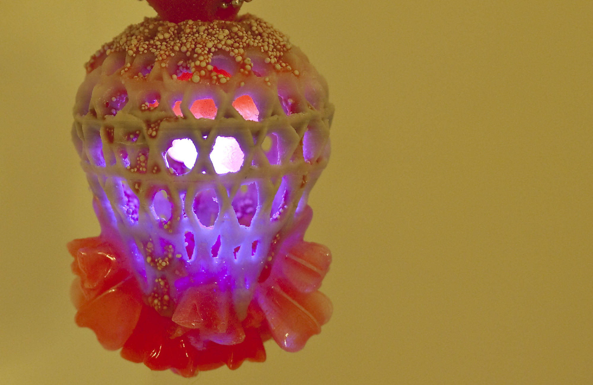
A few issues with the Titan I have run into so far were mostly related to the dreaded clicking/missing steps scenario discussed by many other users in the E3D forum. I am not quite ready to do the rather drastic modification suggested by one user, and for the moment reassembling the extruder really carefully to make sure the gears mesh absolutely perfectly and tightly seems to have done the trick. I am on my 3rd print currently without any problems, but am slightly worried about some of the ‘budget’ filament I own, as it is often 3mm rather than 2,85mm, and even the top notch Faberdashery filament I love to use (and is very precisely specced) seems like a tight fit. After printing the current batch of Christmas decorations, I am yearning to finally try some flexible filament and hopefully see amazingly clean results.

So what are my final thoughts on the Titan modification? It is too early for me to say whether I will love it or loathe it. My old extruder was definitely ready to be replaced, but I need to do some more testing before delivering a definitive verdict. I want to try as many different types of filament and really put the new boy through his paces.I think dealing with clogs could be a bit of a nightmare, but then I haven’t really had many of those over the years – maybe 2-3 per  year. It is clear that some of my processes will have to be modified, such as cleaning out filament from the hotend, and changing filament during a print. I will also have to revisit my spool holder – it might make more sense to have a mounted reel holder now to reduce stress on the filament.

Modifying the printer wasn’t as gruesome as I imagined, and so far everything is working well. I was more than a little surprised to see that the teflon connector in the hotend still looked like new – I had my spare one to hand, ready to replace it. I have been very careful in using my printer over the years, particularly taking care to not run it too hot, and it has clearly paid of.

I hope you enjoyed this account of my experiences  and would love to hear your thought on things you are planning to modify!

Making a PCB – the Jeweller’s way! (Part 1)

Sometimes, having trained as a jeweller is surprisingly useful when it comes to working with electronics. After finally having got my head round the way in which ICs are programmed and used on circuit boards with this handy programmer, I decided that the easiest way to incorporate small-scale electronic components in my jewellery was to make a customised PCB (Printed Circuit Board) – it was time to put the theory into action! Not only would creating custom PCBs save me a whole lot of cash (the components are a fraction of the price of a finished circuit board), but it would also allow me to fully control the shape and size of my PCBs.

The first step in this endeavour was creating the circuit design files. Now, there are a number of ways to do this, and which method you use depends largely on your skill base, the complexity of the circuit you want to design and what method you will be using to produce the final board. There are a lot of great freeware packages available online, the most popular probably being the EAGLE PCB software offered by cadsoft. However, I could not get the freeware version to install on my system, and so decided to look for alternatives in the meantime. Fritzing offers a PCB generator as part of its package, but I wanted to use a software that would let me customise tracks and components easily, while offering a library of ‘pre-fab’ parts to play with until I am more familiar with the pin spacing of components and minimum track widths, so after a false start with the very basic FreePCB, in the end I chose the DesignSpark PCB package (v.7.1). Equipped with a full library of parts, as well as a searchable online database of parts offered by UK electronics distributor RS components, this program was really easy to use and before long I had laid down my first PCB design. For the experts out there it is also possible to make PCB layouts in any vector-based graphics software (such as Adobe Illustrator), but of course you will have to be 100% certain of your design as there are no automatic checks or set design rules in a graphics application. DesignSpark has customisable rules and warns you if components are spaced too closely together or if there are missed connections. It is by no means perfect, and I ended up tweaking some of my PCB designs in Illustrator after finalising the layout in DesignSpark to account for crooked or awkward tracks, as well as adding my logos to the boards.

Once I was happy with my designs, I tried to figure out which would be the best way to get them onto the copper covered particle board. After initially considering using the iModela at our MakeSpace, I decided that maybe the old ways are the best and ordered the chemicals required for photoetching. From my time as an undergraduate at ECA I still had some PNP blue resist lying around the studio, and even though some people swear by the slightly more accurate UV-exposure method for transferring your artwork to the resist, if you have a laser printer at home the PNP is easily the most hassle-free solution. After transferring your design to the dull side of the film with a laser printer or photocopier, the film is ironed onto the thoroughly cleaned and de-greased surface of your PCB board. When ironing on the resist, don’t put too much pressure on the iron, as it can spread the ink and make your tracks bleed into each other. There are some great tutorials online about this process, although I would recommend the use of a glassfibre brush (available from enamelling suppliers) for degreasing your board rather than acetone, as it is more reliable and there’s no need for chemicals.

Once you have transferred your artwork to the board, gently peel off the PNP film, and touch up any imperfections or gaps with a black indelible marker pen. In order to preserve the rest of your board, mask off any areas that are not to be etched with brown parcel tape. You should end up with something like this:

First PCB01

The shiny exposed copper areas are going to be etched away, leaving only the black track marks behind. Depending on which chemical you use, prepare as stated on the packaging and fill a small plastic tub with just enough solution to cover your particle board. Gently slide in your board, and agitate the solution roughly every two minutes either with a feather or by gently tipping the tub from side to side. Eventually, all the copper will have been eaten away by the acid, at which point the board needs to be removed quickly from the acid bath with plastic tweezers and rinsed thoroughly under running water. Don’t ever leave your board unattended in the acid, as the acid can undercut the tracks if left too long. Some people have also successfully used the sponge etching method, but I prefer the traditional way as you have a lot less direct contact with the chemicals. After the board has been thoroughly rinsed, you can remove the parcel tape and the resist with acetone.The end result will look similar to this:

First PCB03See how to finish the job in part II…

On a roll…

Two days ago I finally finished assembling my Filastruder and Filawinder. There were a few last minute tweaks that became necessary once I had decided on my final setup and positioning of the assembly in my studio, such as sourcing a longer cable for the Filawinder sensor and making a stand for the Filastruder to sit on. I had initially planned to go for a fully wall-mounted vertical setup, but the Filastruder is a reasonably heavy piece of kit, and as I don’t quite trust the strength of the walls in my studio, I ended up going with this 45 degree angle tabletop assembly instead, designed to fit the enclosure I am using. Going vertical should always be considered as the superior option, because of the way gravity aids the extrusion process, but you have to work with what you’ve got. Setting up the Filastruder on my workbench and the Filawinder on another workbench opposite gives me enough room between the two machines to drop the filament in a generous loop once extrusion starts, with the Filawinder sensor placed on the floor between them. The sensor cable that was included in the kit was not long enough for this to work (and as 3mm filament needs a slightly longer run before going into the Filawinder, I am guessing it would not be for most people extruding this diameter), but I sourced a 15ft version and the appropriate connectors, which should hopefully see me through all future eventualities.

With everything in place it was finally time to turn on the ‘struder and do the initial purge! Excitement mixed with apprehension as I turned on the heater for the first time and  watched the numbers on the display creep up, eventually reaching the target temperature of 171C. At this point it is really important to give the Filastruder enough time to heat up thoroughly – anyone who has ever used an enamelling kiln will know this as ‘soaking’. While the thermocouple might be displaying the target temperature, this is only measured on a tiny part of the assembly, and it can take anything from an additional 10-30 minutes for that temperature to reach other areas of the machine. Turning on the motor before everything has been thoroughly heated through can lead to disastrous results – in extreme cases even barrel deformation – as the plastic is not liquid enough to let the screw turn freely, putting strain on the motor and other mechanical components. After about 30 minutes I finally felt comfortable enough to turn on the motor. The PLA started shooting out of the barrel almost immediately, initially as very liquid blobs of hot plastic and eventually as filament. During the initial purge, this will be filled with metal particles and other debris, and it could take up to 8 hours to clean out the barrel completely. This gives you however plenty of time to adjust the temperature settings to suit your material, and really fine-tune the diameter of your filament. In my case, it transpired that 171C was far too high for the PLA I am using (Natureworks Ingeo 4043D) and eventually I settled on 155C which gave me a relatively stable output of 2.7-2.8mm filament.

Next: getting the Filawinder to work. 3mm diameter filament poses a further challenge for the winder, as it is a lot stiffer when it comes out of extrusion and thus harder to wind. My initial attempts to get it to work failed miserably, mainly because I had followed the assembly instructions to the letter and cut my length of PTFE tubing in half, making it too short to work in my setup. This resulted in increased strain on the spool which meant the motor was not strong enough to pull the filament and kept getting stuck. Luckily I still had the other bit of the tubing, and a bit of kapton tape later a full length PTFE tube means that the Filawinder is now working like a charm. This is really important for getting a consistent diameter – even moving the sensor during winding can mess up the fragile dynamics that exist between the extruder and winder and be the difference between producing excellent filament and something ready for recycling. After six hours my initial purge was complete and my first spool of filament all wound up:

FirstPLA01Of course, its contents will now be going in the bin as the contaminants mean the material is unsuitable for putting through a 3D printer or re-extrusion, but I’m still proud I made it this far and now have a working setup to extrude my own custom filament. More to follow soon…

M3D – my tiny blue Mini Micro has arrived…

After backing the M3D Micro campaign on Kickstarter last year – one of the most successful ones ever to be launched with nearly 12.000 backers pledging around 3.4 million dollars – it has been a long wait and an even longer journey through 3D printing wonderland for me, most of which has been documented in this blog. When I decided to back the Micro, I did so mostly because of my very tight budget at the time – the $299 price tag was very attractive, even with an additional £120 factored in for shipping and import duties. Then the long wait began (the success of the campaign meant mounting delays and revised delivery schedules) and eventually the pressure of getting my PhD finished motivated me into diving into my savings and getting the UMO+ kit (which also took nearly 3 months to arrive from ordering – 3D printing is apparently for the patient). I have learnt a lot since then, and clocked up many hours reading forums, adjusting Cura settings and tweaking models to get that perfect print out of my UM.

So when I finally got the email to say that my Micro was ready to be shipped out in June, I was excited to scale up my operations with the addition of the tiny blue cube, but also wondering if I still really needed it now that I was churning out top quality prints in all sorts of materials with my UM. But then I saw the Mini Micro!!! I think I had not initially realised quite how tiny it would be, so when the box arrived (including some extra rolls of filament) I was quite taken aback both by its size and weight. This little printer has to put a new meaning to the phrase ‘portable’ – with a slick little body injection-moulded out of thermoplastic (available in blue, green, orange, black and silver I think), and the potential for an internal spool and filament path (I prefer to mount mine externally on the back to see what’s going on) this is the perfect printer to take on holiday, your mum’s house, college, your nearest Makerspace…anywhere really. While I know of a few people who claim the UM to be very portable, and who do take it along to events, I would never consider that as an option – even the UP! felt heavy to me when I lugged it around Dundee for an event, and that is a lot smaller than an UM. The Micro however, would be very easy to take anywhere – it weighs next to nothing and there are very few external parts to contend with. Box it up, stick it in your handbag, off you go! It is also very easy to move around different rooms of the house – as I type this, it is sitting next to me on the arm of my sofa, printing away happily and reasonably quietly. It looks and feels almost like a toy – a very advanced toy, but a toy nevertheless.

Now for the more technical aspects of the Micro. Its design reminds me a lot of the Rapman – a Z axis in each corner, with a central double y axis supporting the printhead and sliding along two x axes. All axes are direct drive, with the Y axes being rotated by a long metal rod connected to a motor and a double belt system (the belts look tiny and somewhat vulnerable). The platform is static and unheated, which will make printing ABS practically impossible if my experiences with the UM are anything to go by. Printing PLA seems to work like a charm, and I have had no problems with platform adhesion so far. The extruder is of the direct drive variety, and I can hear the small fan inside the enclosure whirring away busily when it’s printing – there are no external fans like on the UM. The extruder has an automatic filament drive, with a shielded bowden tube connecting to the internal spool holder (located underneath the printbed), and a tiny hole for feeding in filament externally. The Micro takes 1.75mm filament – handy for me, as it will now allow me to use any filament in my setup, and I love that they have enabled their customers to use ANY filament rather than just the one sold by them. The trend of companies and re-sellers trying to push the proprietary filament model is worrying and needs to be opposed vehemently by consumers. Altogether, I really like the way the printer looks and its handy size, but of course the proof will be in the pudding and the prints it manages to turn out.

So far on that front my experiences have been mixed. When I first got the UM, trying to print my Cocoon shape was a nightmare, figuring out the settings, raft, temperature, z-hop, retraction and speed. However, slowly but surely I was starting to get great results, with the help from many people on the UM forum and by trial and error. The Micro is far more consumer oriented than the UM – it comes with its own proprietary software, which uses the Cura engine to slice the model and then a spooler to translate the Gcode to the printer. It is meant to be truly Plug-and-Play – upload your model into the software, drop it on the virtual platform, choose from a few quality and infill settings, tell the printer what filament you’re using (the M3D filament even has a ‘cheat code’ with preset optimum temperatures) and press print. There is absolutely nothing wrong with this, especially if you manage to find a setting that gets good results with your model. And I think the average user, who wants to download and print something from Thingiverse or Youmagine, will find that the Micro produces very decent prints. But I am already getting the feeling (and the jury’s still out – so far I have only printed two models on the Micro) that this printer would be capable of so much more in terms of speed and quality if there was an option to tweak the setting in Cura and then send the file directly to the printer, or if the proprietary software had many more adjustment options. I really hope that in the future this will be possible – the original Kickstarter campaign promised open-source software compatibility, and for me this is an important aspect of optimising print quality. Another tiny bugbear is the fact that is needs to be plugged into my computer at all times – quite annoying on longer prints, and not as handy as having an SD card to save models on, although I think opinions are generally divided on this matter.

Altogether I am pleased with my pledge – for a product to arrive on my doorstep at all is quite good, considering the many failed Kickstarter campaigns out there. I can see this printer producing good results with simple models as it is, and coming in really handy for taking to workshops because of its size. Whether it will eventually be able to match the fantastic quality of my UM remains to be seen – watch this space! Would I back it again, knowing everything I know now and with the market having moved on considerably in the last year to give us affordable, high-quality printers like the Printrbot Play? Who knows – we’ll see how capable and handy it is in the next few months, and whether its great portability outweighs other drawbacks. For now I am really enjoying my tiny blue cube…


Filastruder Build … Electronics

After receiving my hotly anticipated Filastruder kit, I couldn’t wait to put it together. Starting with the mechanical build, completed over the course of a few afternoons, things seemed to be going smoothly. I had ordered the enclosure kit to go along with the Filastruder, and after a slight hickup with the interior fit of the upgraded v1.6 motor that Filastruder creator Tim Elmore helped me sort out quickly and efficiently via email, my small-scale home extruder was ready to be imbued with electronic life.

This was the part I had been nervous about from the beginning, and even more so as I read the sparse instructions included with the kit. While I have accumulated some experience with soldering PCB assemblies over the last year, and my Arduino skills are improving all the time, doing wiring on a much larger scale is not something I am totally comfortable with yet. I think mostly I struggled with visualising what the end product was supposed to look like – how the wires are held together (soldering or crimping?), how long the wires are supposed to be, how everything fits in the case with the motor. I found very little on this subject on the Solidoodle Forum, the first point of call for any Filastruder owner, and what I did find looked positively lethal and not something I would want to run unattended in my studio. I read on the forum that the extrusion process takes between 8-12 hours or even longer, depending on how much material you are extruding, and I felt that I needed to be completely comfortable with running the extruder for that length of time without worrying about electrical fires. So what to do?

The first clue I found when I finally had the time to get stuck into the electronics assembly were a few large crimp connectors that had been included to wire up the various switches. If you have been following my blog you will know that I have recently developed a bit of a thing for electronics crimping – albeit on a much smaller scale. Crimps are a great and very reliable way to form an electrical connection, and my interest in the huge variety of colourful larger crimp connectors had been stirred already during a previous visit to Maplin. Learning from my previous forays into crimping, I decided to make another trip to pick up some more connectors as well as the appropriate crimping pliers. If you are going to get involved with crimping larger style connectors, a pair of ratcheted pliers is absolutely essential – and not the right place to skimp; your wrists will thank you for using a decent pair that exerts enough pressure to form a secure connection the first time round. Armed with my new tools and an excellent YouTube tutorial on electrical crimping, I decided to tackle the switch connectors first:

Filatronics04After a few unsuccessful attempts and failed connections, the results of my crimping efforts were starting to improve and the wiring was beginning to take shape. The Sestos controller has screw terminals, so I attached ring terminal crimps on the ends of the wires to create a better connection than I would have by just simply attaching the bare wires. After a few more hours and some wasted crimps, this is what I ended up with:

Filatronics01The thermocouple posed another challenge – its two large prongs did not fit well into the screw terminals, and leaving it sticking out straight would have interfered with the case. I resolved this issue by attaching two more ring terminal crimps on one end and two small spade crimps on the other (hidden underneath badly applied heatshrink in the image):

Filatronics02The final adjustments I made was to use a JST connector terminal soldered to a small bit of stripboard to attach the fan and add female header crimps with housings (taped together with their male counterparts with electrical tape for a secure connection) on the heater wires, as I wanted these two elements to be easily detachable if needed.

Filatronics03I also made the decision not to ‘hack’ the original 12V power supply cable as suggested in the instructions but to use a screw terminal barrel jack instead as it seemed neater and more flexible should I ever need to replace the power supply.

At this point I would like to add that all of these modifications and build strategies were my own and should in no way be taken as gospel – if you do things in a similar way as described here when building your kit it is entirely at your own risk. I am still feeling my way around electronics and figuring out the best way to do things. Similarly, if you feel I made a mistake or want to suggest an improvement, please get in touch as I would welcome any constructive advice!

That’s my Filastruder fully assembled now, including cramming the finished electronics into the case. I have not had a chance to try it out yet, but I can safely say that I have finished the job to the best of my abilities. The Filastruder kit was certainly one of the more challenging things I have done so far, despite great email support from Tim. Can’t wait to get going now!!!

Filastruder…unboxing!

This week I finally got the shipping confirmation for my Filastruder kit. After a bit of wrestling with Parcelforce and paying the appropriate customs charges (don’t get caught out by these if you order stuff from the US – at the very least you’ll have to pay UK VAT!), I finally took my little brick of a parcel home. Unfortunately, it could really not have arrived at a worse time for me – between speaking at the Handmade by Machines symposium last Friday and giving a paper at XcoaX 2015 next week. So, having no time to put the ‘Struder together for another week at least, I thought I’d do a small ‘unboxing’ photoshoot to get it out of my system and inspect the contents of the package in eager anticipation…

Filastruder01

It might not look it, but this parcel packs a real punch in terms of its contents…

Filastruder02

…most of which I have yet to identify. Most intriguing bit spotted so far: a huge drill bit that has been filed down in order to create the internal lead screw of the extruder.

Filastruder03

And here are the contents laid out in all their glory. I ordered the whole enchillada, so what you see here are the both the Filastruder and Filawinder in bits, as well as a complementary pound of ABS pellets. I have already procured 12.5kg of PLA pellets for my research, and I can’t wait to feed these to the ‘Struder.

Another thing I was able to fit in between writing my paper for next week and doing the unboxing was to start printing the additional parts required to make the kit work. There are various ways to set up the Filastruder, and the design of the hopper depends on the way you decide to orient the extruder. My studio is starting to burst at the seams (especially since the Ultimaker entered my life) but luckily there is still a tiny bit of suitable wall space at the back, so I decided to print a vertical hopper mount that takes 2L bottles as hoppers from Thingiverse.

Filastruder04

I chose ABS and 100% fill, as this part comes under a lot of strain and needs to be able to take quite a bit of weight – it might have been total overkill, but better safe than sorry. Can’t wait to put it all together…watch this space!

The Wilderness of Micro Jargon or how I deciphered prototyping langugage

It has been an interesting week here at Smart Central, most of which I spent wrestling with the helpful language used on websites selling components and in their respective datasheets. Even though I have now been trying to get serious about prototyping for more than three years, some instructions given with regards to how to activate certain functions offered by components still baffle and confuse me deeply. So much prior knowledge is just assumed to exist on the part of the creative technologist by the authors of these sites and datasheets, and unless you happen to know someone you can ask what something means exactly, and more importantly how to execute a certain instruction, you run the risk of ruining your components. So I thought I’d write this post about my recent experience with the Adafruit Standalone Toggle Capacitive Touch Sensor breakout.

In theory, this is a beautiful component to use to Toggle Capacitive_1375incorporate a touch sensitive switch into your project – you can even replace the integrated touch pad with a conductive surface to make touch sensitive keys that blend in more discreetly with your project by soldering a connector into the pin below the touch pad. There is a momentary version of this sensor available, which is only active when contact is made, but for my current purpose the on/off toggle function works nicely. Now, because space is at a premium when working on a jewellery scale, even the tiny dimensions of this sensor (about 1.5cm x 2.5cm) were too big for my project and I decided to be daring and simply lop off the redundant integrated touch pad and status indicator LED with a jeweller’s saw. I don’t advocate this as the best way of quite literally ‘hacking’ a component, but in this case I felt the value of the learning experience outweighed the risk of ruining the sensor (I bought a spare just in case). However, much to my surprise the maimed component still worked perfectly afterwards – I made an educated guess about the connections I was savaging, and it seems to have paid off. Great – so far so good!

The next step is where things really started to unravel for me – I wanted to make use of the automatic timer function the sensor had to offer. I had read the following instructions in the Adafruit guide for this part (which covers all their touch sensors but none in greater depth):

It also supports a configurable time-out to turn off the output automatically after a delay. To select this mode, cut the ‘TIMER’ jumper and connect a resistor & capacitor to the TIME pin. For a circuit diagram and resistor/capacitor calculations, see page 13 of the datasheet.

You can also just connect TIME to Vdd and the chip will turn off approx 15 minutes after being turned on. Connect TIME to OUT and the chip will time-out approx one hour after being turned on.

Wow. There are a lot of assumptions of prior knowledge in that paragraph. What is the ‘Timer’ jumper (or indeed a jumper)? How do you cut it? Does the second part of the paragraph about the pre-programmed time-out function also require the jumper to be cut? Do you have to add a resistor/capacitor in that case? I decided to look at the datasheet to gain clarity. Unfortunately, the datasheet is not for the actual breakout board, but for the processor used on the breakout. It is highly technical. It did not address any of my questions, as it is clearly written for a highly specialised audience of electromechanical engineers, who know exactly what they’re doing. I was just about able to decipher some of the instructions relating to the timer function, but what I really needed was the map of the different connections and resistors used on the breakout board, also known as an eagle schematic. These I found tacked on at the very end of the guide thankfully, and soon things started to become clearer. Let’s take a look at the back of the board to start with.

A ‘jumper’ I found out after much googling, is a short length of conductor used to close a break in or open, or bypass part of, an electrical circuit. This can be either a separate component, a simple wire or a printed trace on a PCB. In this case it turned out to be the latter – the toggle breakout indeed has two jumpers, one for the timer function and another for the LED indicator of the integrated touch pad (hacked off in my case):Adafruit Toggle 1375 Back modifiedTo ‘cut’ the timer jumper, I discovered, means simply to use a sharp scalpel and scrape away the small bridge between the two larger pads:Timer CutThis, according to the eagle schematic, changes the state of the timer pinout to ‘high’ (or active) by removing its connection to ground (which rendered it ‘low’ or inactive). It is apparently possible to undo this change by connecting the two pads with a blob of solder, but I haven’t tried this as of yet. It is then merely a matter of soldering a wire between the TIME pin and either the VDD pin (15 min auto turn-off) or GND pin (60 min auto turn-off). You can also set the auto turn-off to any interval you like, by adding resistors and capacitors of the appropriate value as specified on the datasheet, but for me 60 minutes will be just fine.

This may seem like a lot of work merely to figure out a single component, but in the process I have also demystified the language used in PCB instructions and gained more knowledge, which is always a good thing…until the next time!

Enter the Filastruder…

So, my birthday has been and gone for another year. Knee-deep in my various PhD research projects, my parents asked me what I would like for a present this year to cheer me up in these stressful times. Imagine their faces when I told them that I would love a kit to build my own plastic filament extruder – probably not quite what they had in mind!

I first read about the Filastruder on Kickstarter about a year ago, before I even owned a 3D printer, and thought it looked really intriguing if a little dangerous. Kickstarter is a great way of finding out about brand new things happening in the 3D printing community, but even though I have been known to back the odd project or two, and so far have not been too unlucky (if you don’t count the month-long delays – Kickstarter is definitely for the VERY patient), most things presented there should be taken with a pinch of salt. Even vastly successful projects like the Form1 often benefit from a period of beta testing, and if your priority is reliability rather than ‘being first’ it often pays to wait a year or two for the technology to get more established and for kinks to be ironed out.

As I have started to experiment a lot more with my printer recently, two things have come to my attention. Firstly, even though PLA is not terribly expensive to buy, the cost soon adds up as I found myself going through filament at a scary rate in the first few months, especially printing out vital components for my research. Secondly, the amount of waste filament also builds up relatively quickly, either from support material or failed prints, which even despite careful planning can and do happen. So, enter the Filastruder. A relatively simple contraption, it is a build-it-yourself plastic filament extruder sold in kit form by the original Kickstarter developers in the US. Since its Kickstarter days, the kit has built up a solid following of DIY filament makers, with some, such as avid blogger Grayson Galisky,  documenting in great detail their filament making experiments on the Solidoodle 3D Printing Community. Of course, since the Kickstarter campaign other filament extruders such as the Filabot and more recently the Protocycler have come to the market – and I am definitely keeping an eye out for the latter. For a UK based option, the Strooder looks promising – compared to the earlier kits those newer machines are definitely heading away from the DIY aesthetic towards a more consumer-friendly look. But for the moment, the Filastruder is the most economical option actually available on the market (the Protocycler and Strooder are both still in their pre-sales phases with release dates estimated for late 2015/early 2016). I have also opted for the spooling kit, as I have run into tangles with loose filament in the past, and the spooler makes the whole assembly much neater altogether.

Making virgin filament is relatively straightforward – buy PLA or ABS pellets or powder in bulk, add a carefully calculated amount of ‘masterbatch’ colourant to the pellets in the hopper of the extruder, mix and start extruding! The pellets need to be completely dessicated to get a great batch of filament, so baking them in an oven for a few hours will really improve quality levels (and of course storing them correctly afterwards). The masterbatch colourant is either sold with the pellets (Colourfabb do this) or you can devise your own methods to make it up – as far as I can tell from the forums almost anything goes, including the addition of powdered metals, wood etc to make exotic filaments. The possibilities that await!!! And it is a lot cheaper than buying ready-made filament. Depending on where you get the raw materials, you could save between 50%-80%.

However, another major appeal for a lot of people will be recycling their failed prints into freshly extruded brand new filament. And this is unfortunately a lot more complicated. The main hurdle to this is really getting your failed prints and waste filament to become tiny granules again – to work in the Filastruder, they need to be less than 5mm in diameter. Plastic can be a really awkward material to work with, and anyone who has ever tried to polish acrylic will know that using powertools of any kind will lead to rapid melting of the material. So apparently will putting PLA in a food processor to chop it up. Industrial plastic granulators are not only prohibitively expensive, but also incredibly bulky – unless you have a massive garage or outbuilding and get really lucky on ebay or a used industrial equipment auction, this will not be an option for you. The second option is using a special plastic shredder. Filabot last year announced the development of their own mini shredder, the Filabot Reclaimer, which looked absolutely lethal in their original promo video and has since been revised to be operated with a hand crank. Within the EU, there is FilaMaker, with their hand cranked mini shredders which look amazingly robust but are expensively handmade to order. These are probably the only viable options for 3D printing enthusiasts at this point – the Protocycler promises to feature its own built-in mini shredder, which would be a massive boon, but who knows if it is still around in a year? If you live in a city with a large industrial base, you might be able to find someone who is willing to let you granulate your waste PLA/ABS. But failing that, it’s really a question I have no answer for as of yet.

Anyway, I will write updates about my new toy as and when it arrives…


Tools, Tools, Tools… part 1

In my quest to make this site somewhat of a resource for budding digital jewellery designers, this post will be about one of my favourite topics: tools. As a jeweller, I am absolutely addicted to nice tools – give me a lovely vintage hammer, an unusually shaped pair of pliers or a set of precision Swiss needlefiles and any birthday/Christmas/anniversary is a great one. Of course, when I started working with electronics this meant that I immediately had an excuse to stock up on a brand new supply of great, sometimes weird looking tools. Here is some advice about what to get that I wish I’d had along the way…

1) Soldering Station – not the right place to save money!

It’s the most essential tool you’re going to get for your electronics work. Scrimping on your soldering iron is just not a good idea – you’re going to do countless joints and maybe even attempt a spot of SMD. You might initially get away with using a cheap, single temperature soldering iron, but as your skills grow so will your expectations of what you might want to be able to adjust on your iron. There are many different models out there and I don’t think I have found my perfect one just yet – but after owning a simple non-adjustable plug-in one (Conrad), a cheapish analogue temperature-adjustable one (Maplin – no numbers were given on the temperature dial, just the categories of low/medium/hot) and a digitally temperature controlled one (Maplin again) I have only started to achieve satisfactory results with the latter. It’s great to be able to adjust the temperature down to within a degree, and it heats up super quickly. It did not break the bank either – it will be a while before I outgrow this one. In electronics, Japanese tools are very highly regarded (in jewellery making too, by the way), and I have recently read somewhere that the Hakko brand is the one to look for if you want to go deluxe, but you’ll have to pay for it (or take a chance on an ebay listing, usually sent from China). On my next trip to Japan (if it ever happens…) I will be flying out light and returning with a suitcase full of lovely components and tools by Hakko. Until then I just discovered that my soldering iron can take the very reasonably priced Hakko tips, and that will have to do. The only other thing I might invest in is a battery powered ultra portable soldering iron, to take to workshops and teaching sessions. Oh, and don’t forget to get one of these brass wire sponge soldering tip cleaners to go with your new iron – the little wet sponge you get included for this purpose is a nightmare and cools your iron down every time you wipe it.

2) Wire Stripper/Crimping Tool

Stripping the plastic casing off a piece wire can be a pain…until you discover this little gadget. Again, some really nifty Japanese ones (the Engineer brand is great) are available on the web and they can be very handy as you can crimp terminals, strip wire and cut screws to length all using a single tool. If you’re going to do a lot of crimping I would recommend getting this tool instead/as well, as the handy ratcheting mechanism will save you from developing repetitive strain injury in the long term and deliver just the right amount of pressure, although it does take some practice to get the hang of it. Working on a small scale means trying to get as little wire mess as possible, and crimping your own terminals is the best way to achieve this.There is an excellent and very detailed tutorial on YouTube explaining some of the different tools and crimping techniques – practice makes perfect! The hardest part must be figuring out and getting all the crimps and terminals you need to do the job at hand…

3) A Breadboard…or three

You want to start prototyping and you want to start now! Well, a breadboard is just what you’ll need. Designed to enable you to fit your components together in test circuits, the choice of breadboards is dazzling.  You can get tiny ones for on-the-go projects in all colours of the rainbow, small ones in a fancy tin, giant ones that hook together to make a mega-breadboard and the standard half-size version you see in all the electronics tutorials. I have been very happy with my breadboard for three years now – it even has some terminals to hook up a bench top power supply, which I initially thought would be mega useful, but have yet to try out! I would definitely recommend getting more than one, as otherwise you’ll be constantly dismantling ‘in-progress’ projects to make room for a new idea. Using a few tiny ones in clusters can also be very useful to keep component groups separated. To start with, one that has labelled rows could be a boon, as it is very easy to get confused what row you’re working in at any one time.

I have put together a suppliers list in the Vault section that I will keep adding to as I find more interesting sources for stuff!

Tiny little Arduinos…

So, in my quest to create fabulous wearable futures for jewellery lovers, I have come to a point where I have to bite the bullet and get deeply involved in the microelectronics side of my research. The arrival of the Ultimaker has pushed my material experimentation to a whole new level, and the moment has finally come to start creating first assemblies of both materials and electronic components for my symbiotic jewellery objects.

Since I started my research, a lot has happened in the world of wearable computing – particularly in terms of miniaturisation, but also to some extent functionality. There seems to be more of an appetite now for developers to release ever-smaller processors and exciting sensors to the hacker community, and more and more people are starting to use them. For someone like me who is just starting out with electronics (and even after extensive reading and research around the subject for the last three years I would still consider myself a beginner) this is a blessing, as a larger user base means more community support in the shape of blogs, forums and user guides. The Adafruit website has a humungous database of learning projects, starting from scratch with the very basics and ranging all the way to the sublime. Another great resource for getting started is the Sparkfun website, which has a great learning section as well as a user forum. If you live in the States either one of these are very handy for you – just choose a project and order the components to go with it directly from the supplier. In the UK, you have to go through third party retailers, but between them they usually have the full range of components available (including some more from other brands).

In my latest efforts to intergrate electronics into jewellery, I was delighted to find that since I last looked in 2013, not one but five new Arduino-based microcontroller boards had been developed in an appropriate size range for wearables. Brilliant News!…Now which one to choose??? For a previous project, I had dipped my toes into using the Arduino Pro Mini 328 5V and 3.3V boards, which are a great little option if you need a lot of output pins and a reset button. I still have two of those in the workshop, and I am sure they will come to be used in the near future for one of my larger, more elaborate pieces. But they are rectangular in shape, and a bit awkward to use within the more rounded, organic shapes I have been making of late. Also they are quite possibly processing overkill for what I am trying to (and capable of) do in terms of programming. They have a similar functionality to the much larger Arduino Uno, which is definitely a lot more than I need at this point, although I like using one for running prototype programs and test the wired connections.

An immediately appealing option for using in my projects were the Adafruit Flora and Gemma, with the latter being smaller, with fewer pins and no serial monitor capability. They are both circular, which is a much easier shape for me to incorporate than the usual rectangular geometries of PCBs. I ordered the Gemma (the Flora is probably a little bigger than I would like for my use), and it is a nearly perfect size for most of my jewellery projects, with the handy JST and USB mini jacks meaning programming and powering the controller is a doddle. However, I am as of yet struggling with the programming – the first example sketch  I tried to load onto it would not work (and we’re not talking Blink here btw), because of the lack of a serial monitor. I have not given up on Gemma, but I might have to postpone until my programming knowledge catches up. Another small controller recently introduced by Adafruit is the Trinket, which I have not yet had a chance to consider, but which is supposed to have the processing power of an Arduino Uno and looks really really neat and tiny…

…Which brings us to the last two new arrivals to the wearable controller market of late, the TinyDuino and TinyLily. Born out of a Kickstarter campaign by developers TinyCircuits,  these are whole systems of tiny microcontrollers and accessories. Essentially built around the hardware of the Arduino Pro Mini and LilyPad series, the TinyDuino is square in shape and comes with an array of development boards and accessories, while the TinyLily is round and merely the size of my thumbnail but still has 8 sewable ports (4 analogue/4 digital) and two power outlets to play with – plenty for my requirements. The input voltage on these two controllers is variable between 2.7V and 5.5V, so allows for use with a large range of sensors and devices. Here is a size comparison of the Flora, Gemma and TinyLily for reference:

Size Comparison TinyLilyWhile the TinyLily is slightly more awkward to program and connect, it has a definite size advantage over the other two that for making digital jewellery could make all the difference. It is slightly more expensive than the Gemma and about half the price of the Flora, but that seems about right in terms of functionality and processing power. Just for comparison, here are the Trinket, Trinket Pro and Arduino Pro Mini Boards:

Size Comparison Trinket

Sizewise they are perfectly suitable for wearables, especially if you need the advanced functionality and processing power – with Adafruit Neopixels for instance. Their rectangular shape makes them a bit awkward for me, but I could see how they would work in the right situation. Now, on to tackling the programming…